Pekka Buttler, June–November 2021
Introduction
‘Ghosting’ and ‘veiling flare’ (sometimes also referred to as ‘veiling glare’ or simply as ‘veiling’) are forms of unintended consequences of how light and lenses interact that – while sometimes allowing artistic impressions – can be a major nuisance in photography. Moreover, as ghosting and veiling flare tend to burden especially older lenses, JAPB readers will likely find the topic especially interesting. Read on below.
Note please, that although veiling and ghosting are visually relatively distinct, the mechanisms that produce them are largely shared. Therefore both veiling and ghosting will be addressed in the same article.
This article is part of a JAPB series of articles on the optical flaws of lenses and you can find the index of the series here.
Veiling and ghosting (a visual guide)
Veiling and ghosting are both forms of (lens) flare, and as the terms are being used somewhat haphazardly on the Interweb (and sometimes also just lumped as ‘flare’), a short, visual explanation is in order:
Veiling
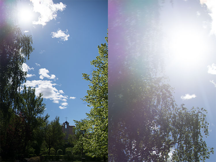
Veiling flare shows as a bright veil around a strong light source, that washes out colours and diminishes contrast. That veil may simply have the colour of the light source, or it may take on a mild coloration (as in this case).

In this example the veil is not white but instead takes on the colour of the orange sun (sunset).

Ghosting
Ghosting shows up as coloured blobs, that sometimes (such as here) reflect the shape of the lens’ aperture).

The ghosting blobs typically form a line starting from the light source and passing through the frame’s centre.

The causes veiling for veiling and ghosting?
Veiling has three main causes:
1) reflections off non-glass surfaces and
2) scattering,
3) reflections of glass surfaces (which are typically referred to as ‘internal reflections’).
Furthermore, internal reflections can – depending on factors that we will explore later – contribute either to veiling or ghosting (or both).
I admit this article is a bit complicated because veiling and ghosting are at the confluence of several, complicated interactions. In the hope of making it simpler, I’m going to start the investigation of the three causes of veiling with the most straightforward element:
Reflections off non-glass surfaces
Firstly, we have the simplest factor contributing to producing veiling, namely: reflections of non-glass surfaces. These happen, because photographic lenses are not just made up from various types of optical glass, but also contain metals and (more recently) plastics. Let’s start by looking at some pictures of lenses.
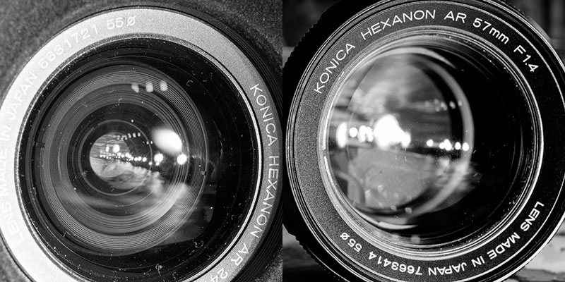
Right: Konica Hexanon AR 57 mm f/1.4
Shot with Sony ⍺7R2, Nikkor 35 mm f/2 (Ai) and Kipon helicoid adapter
What you can see in the left-hand picture above is that a significant share of all the light that enters the front element of the lens is ‘caught’ in the lens’ internals, while only a relatively small share of the light gathered by the front element is subsequently passed through the lens’ aperture to reach the film/sensor. In the right-hand picture the share of light caught within the lens is very much smaller, but not totally insignificant (both images shot comfortably within the lens’ angle-of view).
That lenses (especially wide-angle lenses) gather a great deal of the light, only to then waste it is somewhat beside the point here. The important question however is, whether all that light that hits the lens’ internals (and is not passed through to the film/sensor) is effectively ‘caught’, or whether a part of it hits an internal (non-glass) surface and is reflected back from there (potentially ending up in the final image).
Practically every lens developed in the last 50 years utilises several tricks to minimize the risk of internal reflections. The most important two of these is to use anti-reflective surface treatments (special paints) and baffling.
Anti-reflective paints
This is basically that each part of the lens’ innards is covered in a special matte black paint in order to catch errant light rays. If you’ve taken a close look at these parts (especially if you’ve ever taken a lens apart), you will have noticed that most (almost all) non-glass parts are covered with such a layer of paint. Also, you might have noticed that even the edges of lens elements are often treated with such a layer of paint (the flaking of which is a lens defect known as ‘schneideritis’), aimed at effectively eliminating light rays caught up in total internal reflection.
The choice of matte black paint is obvious when you consider that black is the colour that absorbs all light (and does not reflect any back) and the reason for using a matte paint is that matte indicates a minimally reflective surface.
A perfectly black black would absorb all light we would not see it at all. Instead it would look like looking into emptiness. Problematically we’re not quite there yet, as we can clearly do see the lens innards. Instead, what we have instead (of perfectly black) is a very, very dark grey, that is liable to reflect some light. This where the other trick (baffling) comes into play.
Shiny blades – a vintage exception to anti reflexive paints
Even so, there is one area where an otherwise perfectly matte-blacked lens may still show shiny metal and that is in the aperture blades. The one problem with matte, painted surfaces is that they tend to produce some friction, and there is one moving part in a lens where you will want to have as little friction as possible: the aperture blades.
As aperture blades are intended to move freely and very quickly, typically operated only by a relatively weak spring (this pertains to all but preset and manual aperture lenses, i.e. a dominant majority), minimising friction becomes a prime requirement. Problematically, for some years after the introduction of ‘auto aperture’ lenses manufacturers were not completely convinced that the painting of aperture blades would not lead to potential reliability issues.

This is why you might encounter lenses that have distinctly shiny/silvery aperture blades, such as the Rollei pictured above. This can be especially troublesome on digital sensors, because the (shiny) rear side of the aperture combined with the (compared to film) relatively reflective sensor make for a double-mirror arrangement that allows light to bounce back and forth between sensor and aperture blades.
Baffling
In engineering, a baffle is any kind of wall-type protrusion that is intended to obstruct or disturb the free traverse of waveforms and, especially in liquid dynamics, baffles are crucial. In photography a baffle is a “shroud protecting the optics of an imaging system from being disturbed from stray light.” (wikipedia). In that sense one can see a lens hood to be a sort of baffle, but the main type of baffle I am referring to is to be found on the inner edges of a lens’ optical path.
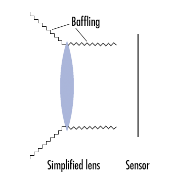
While the real purpose of the matte, black paint is to maximally absorb light and allow as little of it as possible to be reflected back, the point of baffling is – by creating a stepped structure – to channel the few remaining reflections:
a) otherwhere than to a place where that reflection might cause havoc, while;
b) preferably reflecting that light onto another matte black surface where it will have another chance to become absorbed.
Due to the differences in the angles of incoming light (light that has not yet reached the front lens) and outgoing light (light coming from the rearmost lens surface), the angling of the stepped baffling is typically different on the front and rear of a lens (see illustration above and pictures below).

Incidentally, one issue users of cheap lens adapters may encounter is the lack of baffling on the insides of adapters, as thoroughly documented here.
Scattering
Scattering is the second factor that contributes to veiling, and while the mere existence of scattering (as a field-relevant phenomenon) flies in the face 1 of Physics 101, explaining scattering and its contribution to veiling is relatively simple. n.B! Scattering is not a technical term and I will not even attempt to explain this like one would in a degree course in physics/optics.
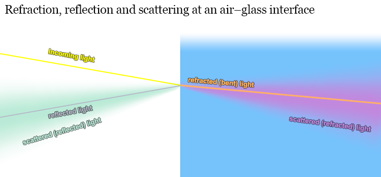
Even so, we’ll need to cover some concepts regarding what actually happens when light hits the surface of a lens (referred to as an air-glass interface). Please note that we here focus on reflections off lens surfaces (reflections off non-glass were already addressed above)
Refraction: We all know that the point of variously shaped lenses using different kinds of glass mixtures (flints, crowns, fluorites, ED’s, etc.) is to refract (technical term for ‘bending’) the incoming light rays so that they – in the end – form an image onto the sensor/film. If you’re reading this article, you’ve likely seen illustrations of how these rays are bent in different ways depending on their angle vis-a-vis the air-glass interface. This is the vanilla, as-it-should-be part of optics and needs little elaboration, especially because as long as everything is vanilla, you won’t encounter veiling or ghosting.
Reflection: Unless you’ve slept through your school’s physics curriculum, you also know that not all the light that hits the air-glass interface is passed through (refracted), because a portion of it is actually reflected away from the air-glass interface. You may also remember that the share of light that gets reflected (not refracted) increases as the angle of incidence (between ray of light and air-glass interface) becomes shallower (which is why you’re more likely to see through the surface of a lake at a steep angle than at a shallower angle).
Scattering: contrary to most illustrations showing ray-paths – not all light is either refracted or reflected neatly in one or another direction. A small share is also scattered, which means that light is either refracted, but not refracted correctly (at the correct angle), or reflected, but not at the correct angle. In effect this leads to that a share of light goes where it – seemingly – should not go. See the garish-coloured illustration below.
Causes for scattering: Reflection and refraction are the core of optics theory. When one thinks of optics and how they work (whether in school or in lens labs), one mainly considers refraction, then factors in reflection, but scattering is – while far from uncommon – not part of the typical calculation.
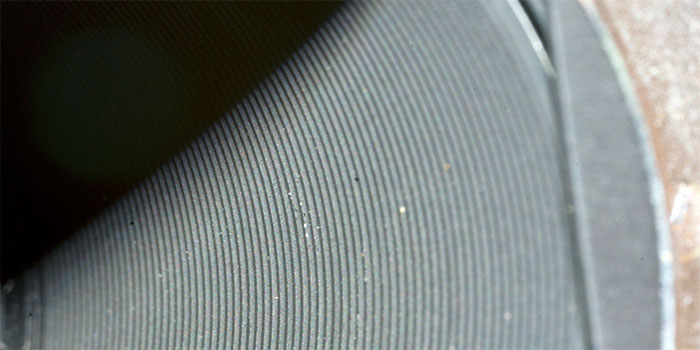
Physically the main cause of scattering is caused by of the nature of light in combination with the properties of the air-glass interface. We don’t need to go into the intricacies of quantum mechanics and photonics, suffice it to say that: while any lens surface seems perfectly smooth to both human eye and touch (and the assumption of smoothness is echoed in optical schematics) – from the viewpoint of a photon – a lens surface is about as smooth as worn tarmac is to a bouncy ball.
While the typical wavelengths of visible light are in the ≈400–750 nanometres (1/109 meters) range, a lens surface flatness is judged at a scale of 150 nanometers. To put this in perspective, take your average tarmac and a one-inch bouncy ball. While you will be able to predict the majority of rebound angles based simply on the angle of incidence, a decent percentage will end up defying your calculations. You can think of these errant bounces as scattered reflections.
Therefore, when you factor in the scale of things, it suddenly becomes obvious why not every photon is reflected or refracted exactly according to Snell’s law (well, actually it is, but the problem is that your understanding of the evenness of your lens surface turns out to be only an approximation). Furthermore, there are differences between worn tarmac and newly laid tarmac, between 40 grit and 160 grit sanding paper. In effect, the smoother the manufacturing process (grinding, polishing, and coating) manages to make the lens surface and the more uniform the manufacturing process manages to make the glass, the less scatter is produced.
Unless the machinist in charge of producing lens elements has preferred working with a chisel (and unless the lens elements have become excessively worn), the amount of scattering is effectively very small, but there are cases where even a very small share can be a very big number. This is a recurring topic with regards to veiling and ghosting and deserves a separate treatment (see below)
Internal reflections
If you’ve read through the preceding paragraphs you already understand the basics of refraction vs. reflection. Now, let’s disregard scattering for a while and focus on reflections. Moreover, let’s – for a moment – disregard the ghosting vs. veiling issue, because internal reflections are liable to be complicated enough as they are.
As said above, the relative share of light that is reflected increases as the angle of incidence (light ray vis-a-vis air-glass interface) becomes shallower. This does not, however, mean that all the light hitting an air-glass interface at a perpendicular angle would pass the interface. While – in most situations normal to a photographic lens – a large majority of the light hitting the lens comes at angles conducive to to passing through the interface, the aggregate share of reflected light (around 5% for uncoated lenses) is not wholly insignificant, especially when you consider that a typical lens has several air-glass/glass-air interfaces2. In effect, the continued development of lens coatings has contributed to that modern similar spec (e.g. 50 mm f/2) lenses conduct a lot more light than their older counterparts, but that’s actually not the most important part.
What is crucial is, that (except for that light that is reflected back ‘out’ from the frontmost lens element’s front surface) reflected light is far from entirely out of the picture (pun intended). Instead, reflected light will end up playing all kinds of havoc with the intended picture. For a simple (and simplistic) illustration, see below:
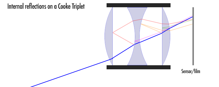
Yup, as promised, a simplistic illustration. I did not even bother to compute all the (reflection/refraction) angles, so they’re guesswork, but the point is that any part of a ray that is reflected is liable to re-enter the picture, but at the wrong place.
If you consider the case of internal reflections, a number of things become evidently important:
• Lens Coatings: Invented in the 1930’s (but less than commonplace until after the war), lens coatings have the potential to significantly lessen the impact of internal reflections. If you develop a coating that decreases reflections by half, you simultaneously improve light transmission and decrease veiling tremendously. Importantly, coatings are not a binary choice (coated lenses / uncoated lenses), but the quality of the coatings matter, as well as whether all lens elements have been coated, or whether only some elements have been coated. The development of ever better (more transmissive) coatings is a continuous endeavour.
• Lens group counts: Given that every lens surface (air-glass interface) creates the potential for introducing new internal reflections, this means that as the number of groups (air/glass interfaces) increases, so does the occurrence of internal reflections. This is why really old (pre-war) lenses typically preferred lens designs that would keep the group count at a minimum (Petzval’s (2/3 groups), Tessar’s (3 groups), and Sonnar’s (3 groups) instead of Planar’s (min. 4 groups), and Ernostars (4 groups). One can – without resorting to hyperbole – say that modern high performance prime and zoom lens designs (with group counts in the double digits) would have been impossible without the development of highly effective coatings. Coatings and element counts also have a significant combined impact on T-stops, but those we sill have to return to at a later stage…
• Scales: Admittedly, the sum effect of such reflections is typically not very strong. Even if we assume the hypothetical Cooke Triplet used above was one of the original, uncoated variety, ≈73 % of a ray would make it all the way to the film/sensor and do so in good order, while the remaining ≈27% would be divided into
a) reflections that are reflected back ‘out’ of the lens, thereby not contributing to forming the image (and not contributing to veiling),
b) reflections caught in total internal reflection, thereby also not contributing to veiling,
c) reflections ending up so way off, that they would be caught by the lens’ baffles or camera’s mirror box,
d) scattered reflected light (see above), and
e) reflected light that would reach the film/sensor, but do so in the ‘wrong’ place…
So in effect, the relative share of light that – due to internal reflections – ends up on the sensor somewhere else than where it should is minuscule, but let’s next have a look at the question of scales and magnitudes and why a promille can be a big effing deal in optics (and not only in alcohol tests).
Scales and magnitudes
As a former colleague with a degree in pharmacology told me once: “Mediaction is all about dosage. 365 cups of coffee a year might mean energetic mornings if you drink a cup every morning, but it means sudden death if you drink them all during the same day. The same goes for every medication and every beverage ever invented.”
And the same goes for reflections (whether off glass or non-glass surfaces) and scattering as well. Assume one’s dealing with a 1900’s uncoated lens element. 95% of light passes through each air-glass interface, which means ≈90 % make it through the lens and the rest is reflected (first from the air-glass interface, then from the glass-air interface. Repeat this a couple of times (say 3 times for the Cooke triplet) and only ≈73% of all the light that could (in the absence of reflection) reach the film/sensor will do so.
Now assume that out of all the light that is either reflected or refracted 10% is scattered enough to not land on the correct photosite/photoreactive particle. That sounds like a lot, until you consider that that 10% is divided on a relatively larger area. Say you’re making a sunset photo (like one of the images above) and your sun is 400 pixels wide (giving it an area of ≈ 1250 pixels). If 10% of the light that should hit one of those 1250 pixels is spread out around the circumference of the sun onto an area 1600 pixels wide (≈5000 pixels in area), then (on average) each pixel will receive only 2,5% of scattered light. That no longer sounds so bad, even when one considers that most of that scattered light will end up close to the sun…
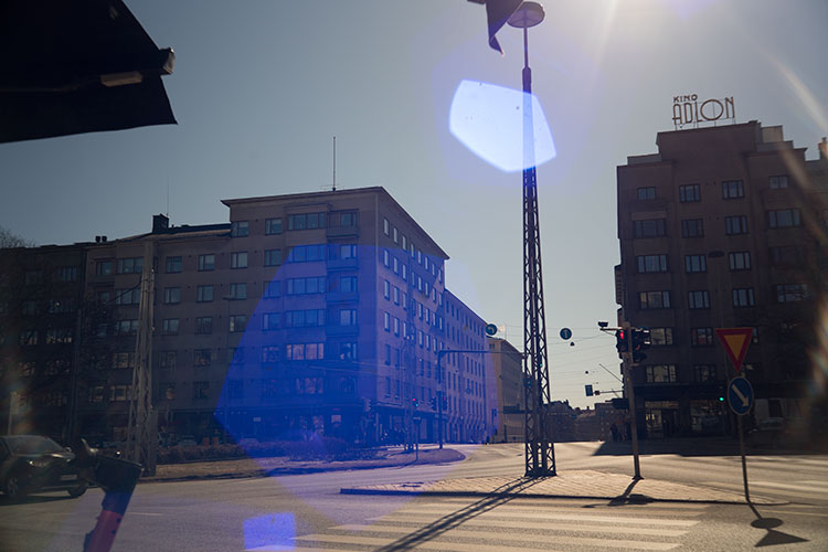
But, consider the magnitudes. Say you’re shooting up into the sky and end up with a shot like this:

Canon FL 55 mm f/1.2 @ f/5.6; Sony ⍺7R2, aperture priority, WB auto, ACR default
In the final image the sun has a brightness value of 100%, while the blue sky next to it (around the wispy clouds) has a brightness value in the 45–60% range. But these values are not ‘real’ but simply the result of the camera trying to “expose correctly”. In reality those pixels that make up the sun are so much brighter than the surrounding sky that a 100% brightness value simply means that the photosites are fully, utterly, and irretrievably maxed out 2. In actual fact, the sun’s brightness will not only be double that of the blue sky around it, but several orders of magnitude greater.
The illustration below shows the relative brightness value of a number of pixels along a line selected based on that the sky along that line was (to my eye) reasonably evenly bright. (If the pixel contained a cloud or other, an adjacent pixel was measured).
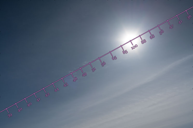
While we can blithely disregard the sub-40 values in the corners (the remnants of vignetting at f/5.6), we can see that the blue sky (at this exposure ) has a natural brightness value between 40 and 45. Whatever’s higher that that (45-60) and significantly higher than that (60-90) is the result of veiling, meaning that (take for instance the 56-value, relatively close to the image centre) a large part of the frame has received significant extra photons by diverting a minuscule share of those photons that should have landed on the part of the frame where the sun is rendered.
The point is that if you’d be granted one percent of someone’s net worth, you’d better choose someone like Warren Buffet (that’d make you rich), not someone like me (you would only gain a couple of vintage lenses and some beer money).
Some further characteristics of veiling
Now, admittedly, in the picture above, the veiling effect is not that bad, because
a) we kind of expect there to be some added brightness in the vicinity of the sun
b) there is not really anything in the picture at that location which that veil obscures.
But things start being significantly different (and a lot more annoying) whenever that veiling obscures detail that we would very much like to record. Take the two pictures below as an example.
(right click and open in new tab for bigger version)
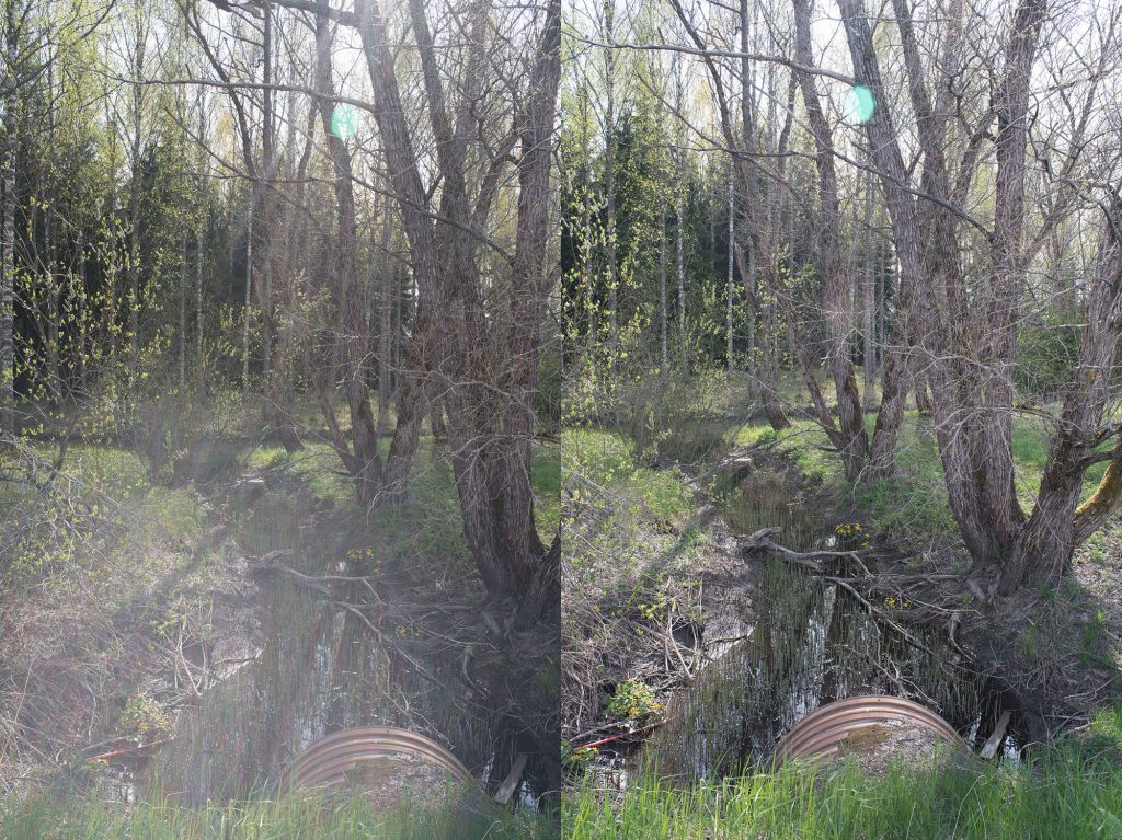
Looking at that pair of pictures (ACR default, only resized) you will notice that the veiling (in the left-hand side shot) significantly lessens contrast in the entire lower half of the image. Unless this is expressly what you desired, it can be a major annoyance. You will also notice that a very minor change in how the lens was angled (during shooting) produces a big difference in the extent of veiling. This brings us to an interesting and (albeit, at first sight counterintuitive) logical aspect to veiling.
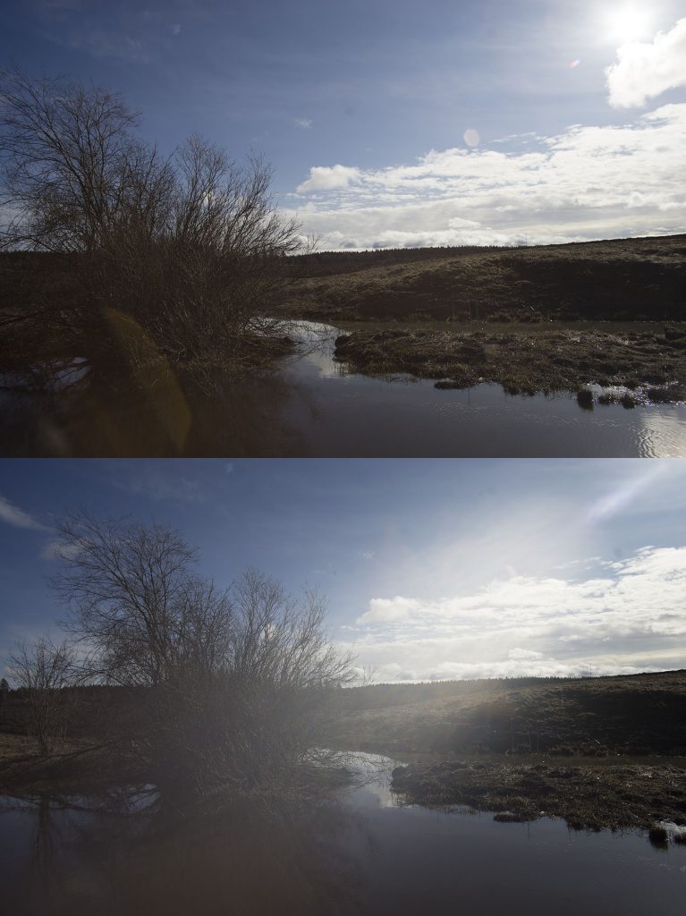
Importantly, just making sure the sun (or other strong source of light) is not in the frame does not help. The reason for this is simple and it is that your lens regularly captures an image that is significantly wider than what shows up in your frame (or optical viewfinder). Therefore, even though the sun is not visible for you (within the frame) it is within the lens’ image circle, and is therefore almost as likely to produce veiling as if it was in your frame.
In fact, with some lenses the effect of the veiling flare may become even more pronounced if you shift your frame to exclude the light source. In the example pair below the first picture was taken with the sun in the top right corner of the frame, and for the second picture was taken only seconds later with the sun just out of the frame. While the upper shot shows very little veiling, it does show some ghosts – and while the lower image shows no ghosts, it shows massive veiling. And all this only thanks to a very minor shift in the angling of the shot.
(right click and open in new tab for bigger version)
Ghosting
I’ve – until now – mentioned ghosting a couple of times, and admitted that I’ve wanted to postpone treating ghosting. Assuming you’ve made it this far, now is the time for me to address the bogeyman ghost in the room – not because ghosting is especially difficult, but because it adds a complication that I’ve wanted to avoid this far.
Let me start by repeating one of pictures I already showed you:
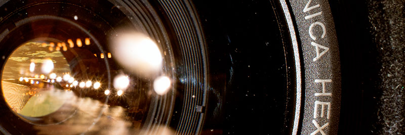
What you see in this picture is that some of the light from the dual LED headlamp I used to illuminate the lens for the shot is reflected. More importantly, it is not only reflected once, but several times (meaning: not only from front-facing surface of the frontmost lens element, but a large number of element surfaces). And of all those myriad reflections visible, only one is pure reflected light, whereas all others are the result of several refractions (and – typically – one reflection).
How does this illuminate the concept of ghosting? Think of it like this: When using a lens on a camera, you have light only on one side of the lens, and a lack of light on the other. So all light that lands on the film/sensor has had to come through the lens. Further, I’m going to introduce a rough concept pair: inbound light and outbound light – hoping to help you conceptualise a crucial relationship.
Inbound light is light that is heading front-to-back: through the lens towards the film/sensor; Outbound light is light that is heading back-to-front: out from the camera and away.
Every time a light ray is reflected it is changed from inbound light to outbound light and vice versa4. So all the reflections (outbound light) of the headlamp’s LED’s (inbound light) you see there have been reflected either once (most likely), three times (close inspection shows some indications), five times (unlikely) or more (hardly).
Consequently, should light be reflected twice, four times or more (even-numbered) times, the result will be inbound light that is liable to show up as a blob of light on the film/sensor. I’ll again repeat an earlier image:
The ghosting blobs typically form a line starting from the light source and passing through the frame’s centre.
This image offers a very nice illustration of ghosting, because there are many ghost blobs and they show up in a very pretty line. Most important though is that the image illustrates another point. Please count the ghost blobs, and consider that the lens in question has 7 elements in 6 groups.,
Because there are undeniably more ghosts in that image than there are element groups in the 50 mm f/1.4 Hexanon lens. Moreover, if you look closely, you’ll see that some ghosts are significantly more pronounced than others, indicating that some ghosts are the result of having been reflected twice (relatively strong blobs) and some having been reflected four (or more) times. Finally, you’ll maybe notice that some of the blobs clearly echo the shape of the aperture while others do not, indicating that some of these double (or quadruple) reflection originate on one side of the aperture and others originate on the other side…
What does this mean (re: ghosting)? It means that ghosts are caused by even-numbered reflections: inbound light that has first been reflected once (changing it to outbound light), only to be reflected once more (changing it back to inbound light). Granted, even with an uncoated lens a double reflection cannot be more that 1/400th of the original intensity and on a lens with modern coatings we’re talking about less than 1/10000. But (think of the scales and magnitudes -bit above) that can be plenty. There is therefore only one loose end that needs tidying up…
Air-glass interface shapes
We’ve established that lens surfaces (air-glass and glass-air interfaces) are primarily intended to act as refractive (light-bending surfaces), they also have the potential to act as reflective surfaces. Therefore – for the intents and purposes of looking at ghosting and reflection – it makes sense to also view lens surfaces as mirror surfaces.
If you have any interest in optics (and I assume you have), you’ll know that concave mirrors gather light and convex mirrors disperse light and straight mirrors do neither. Why is this relevant?
Because – if we assume that a reflection does take place – the shape of the lens surface that causes the last (inbound) reflection has a huge impact on whether we deem the result to be ghosting: a clearly delineated light-blob; or veiling: a non-delineable, potentially even uniform increase in illumination (resulting in a lessening of contrast).
While it is a simplification to say that the shape of the reflective element defines whether the resulting reflection is veiling or ghosting, that simplification has so much power that I’m going to let it stand.
P.S.
Yup. I started writing this article in June 2021 and did not finish it before November of the same year. Obviously I did not use all that time to create impressive illustrations. Granted, I’ve had a fair bit of other stuff on my mind as well during this time, but the main reason for the prolonged writing process is that the article turned out to be way harder to write (and write in a way that was logical and consequent) than most others. Sorry, and enjoy.
Footnotes
1 Note please. I’m not saying that scattering is contrary to physics, but I do acknowledge that scattering is typically not covered in basic courses in physics/optics, due to the simple reason that it’s not productive to do so. Scattering – just like e.g. chaos theory – is a complication educators can safely postpone until students are advanced enough to be able to face the complication without going into dissociative fugue or headless chicken mode. Even so, the fact remains that scattering (as a phenomenon) is rarely covered in introductory courses in physics/optics – a land where a simplified understanding of Snell’s law reigns supreme.
2 For example: A classic double gauss lens (such as the 58 mm f/2 Biotar, anno 1939) has 6 elements in four groups, meaning 8 air-glass interfaces. If every such interface loses 5% of incident light, the aggregate effect is a ≈34% loss. Should you update that design with the best modern coatings, you would lose only 0,5% per interface, leading to a significantly lower aggregate loss of ≈ 4%
3 There is a simple way to ascertain how badly “maxed out” the sun is. Put the camera on the tripod, and take a picture with the (noon +/- 5 hours) sun in the relative centre of the frame, using any automatic exposure system (aperture priority, shutter priority or ‘program’). Note the settings. Switch to manual and start taking a series of shots in which you – step by step – lower exposure by a stop (halve shutter speed / close aperture a stop / lower sensitivity a stop). Depending on the settings your camera&lens -combination allow, you might be able lower exposure by half a dozen stops. Take those pictures back to your computer and see if you’ve managed to not max out the sun. My guess is that the answer is: no. If you have a ND (neutral density) filter handy, you can go further than aperture/shutter/ISO allow, thus reaching a situation where the centre area of the sun is not maxed out.
If you reach the point at where the sun is no longer maxed out at – say – 10 stops underexposed, this means that the sun was maxed out by between 29 and 210, meaning ≈ a factor between 500 times and 1000 times. Very likely, your ‘sky will at that point be entirely black and (if you have enough resolution) your image will allow you to count the sunspots.
4 Yes, I know that this is not 100% true, because there is the phenomenon of total internal reflection, but as TIR is effectively out of the picture (pun), this omission is justified.