Pekka Buttler, June 2021
Introduction:
Colour casts can mean two different things: The first (and more common) issue is a significant colouration of the entire resulting image, typically due to lens elements that change the spectrum of light coming through them. These colour casts are physically very different and will be treated separately here.
The other issue is typically associated with specific types of lenses on some types of sensors and mostly affect the off-centre areas of images and are the focus of this article.
This article is part of a JAPB series of articles on the optical flaws of lenses and you can find the index of the series here.
What are non-uniform colour casts
One of the joys of adapting legacy lenses to mirrorless interchangeable lens cameras is that all those rangefinder lenses of yore – lenses that could never be used on SLR’s because of the typically short flange focal distances of rangefinders – can now be adapted on the latest and greatest mirrorless bodies. And indeed, plugging that > 60 year old Leitz lens on your new mILC might be a revelation. Or it may be a disappointment.
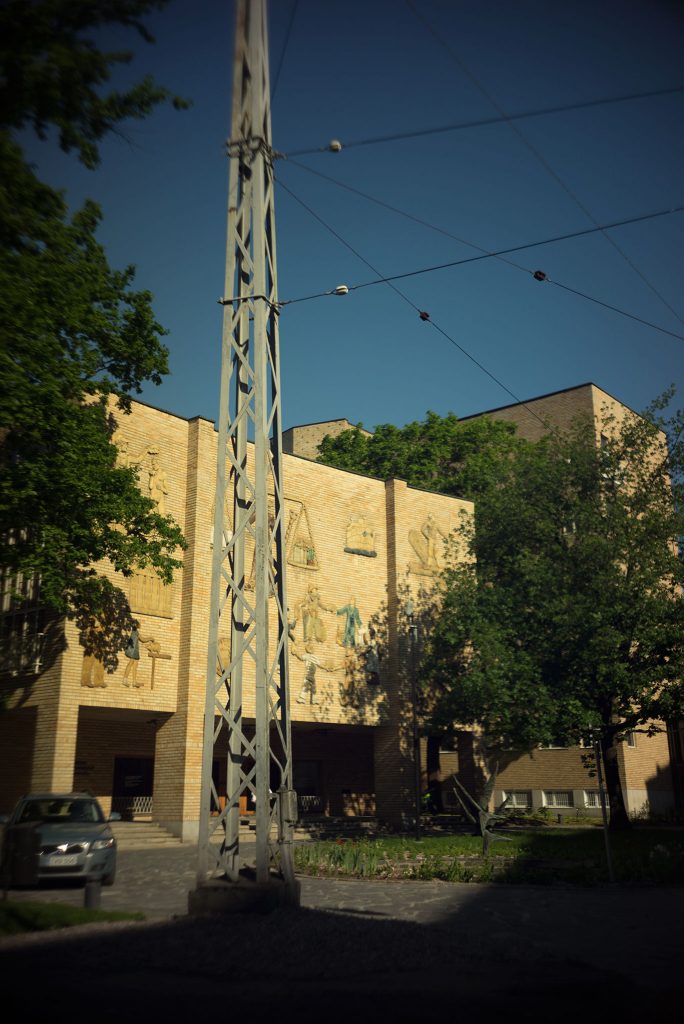
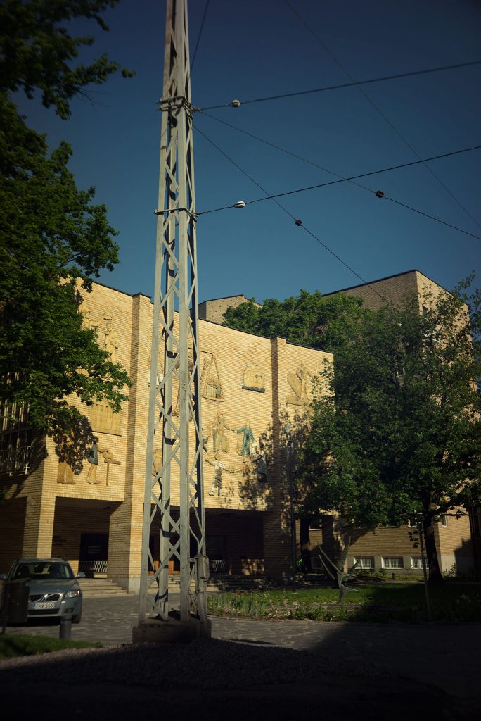
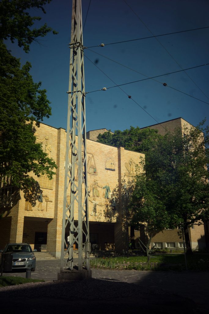
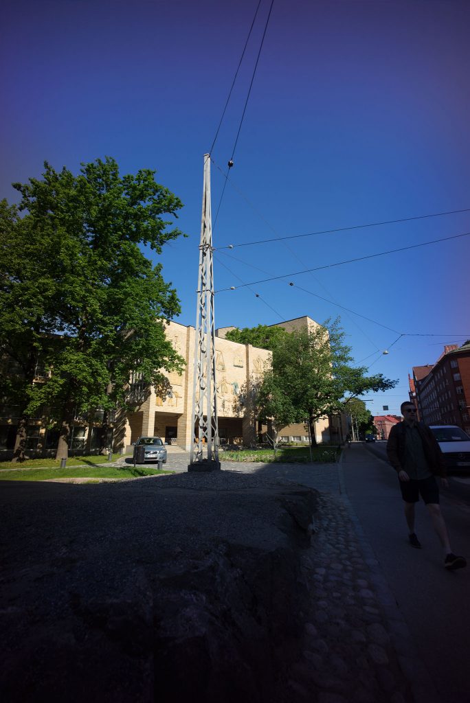
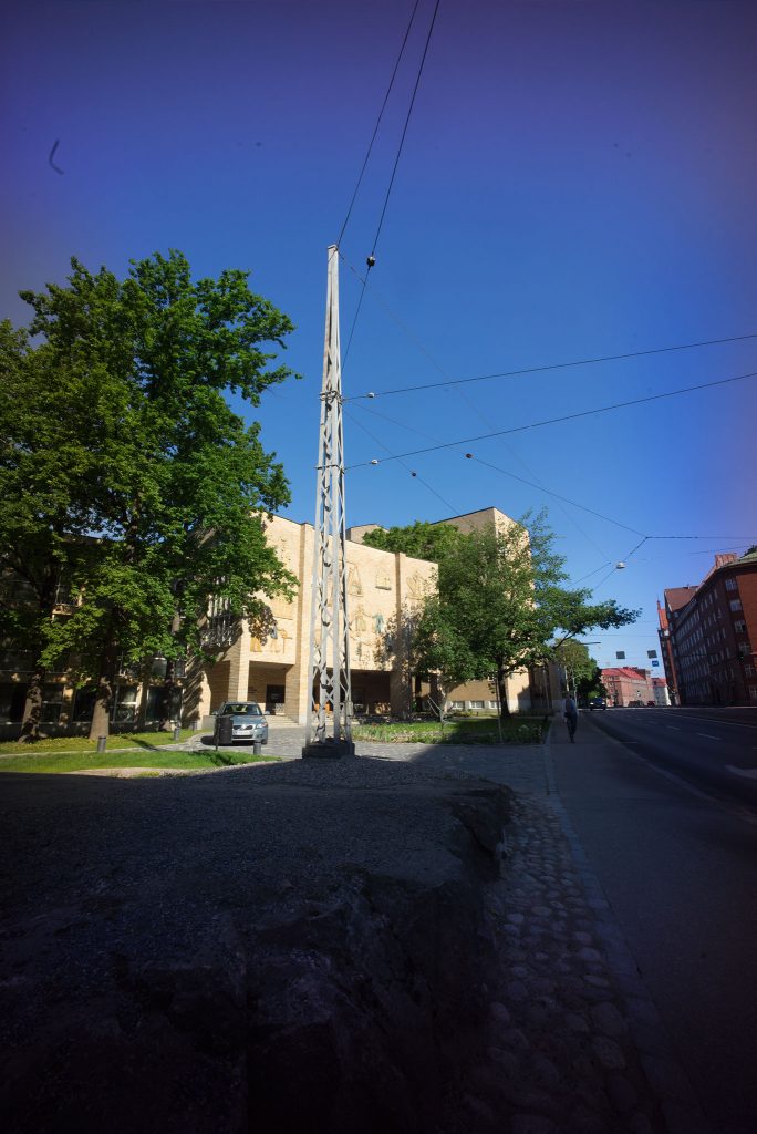
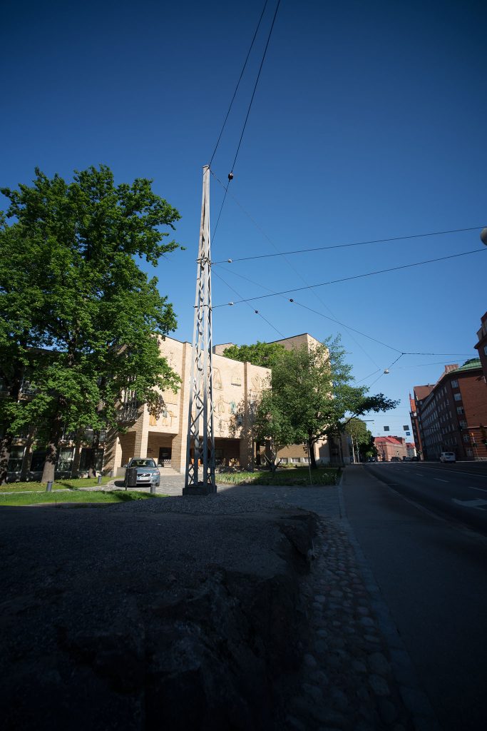
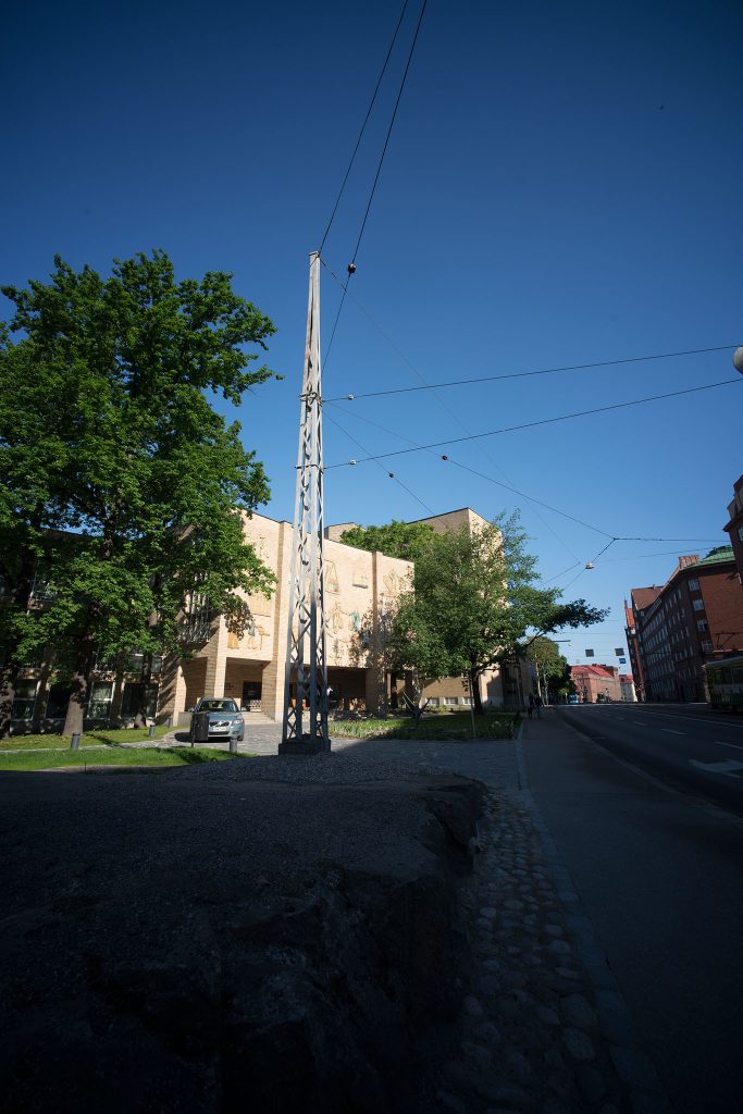
Problematically, some old rangefinder lenses lead to less than pleasing results on many modern mILC’s. They produce extreme vignetting (will be addressed below) and massive blurriness (not the subject of this article) as well as a baffling corner colour cast (such as in the example pictures below). Because these effects are typically not a problem in the image centre, they are mostly referred to as corner colour casts.
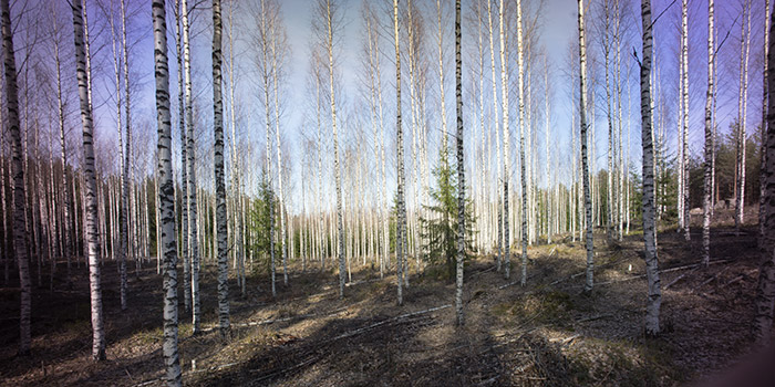
(cropped, resized, some vignetting removed)
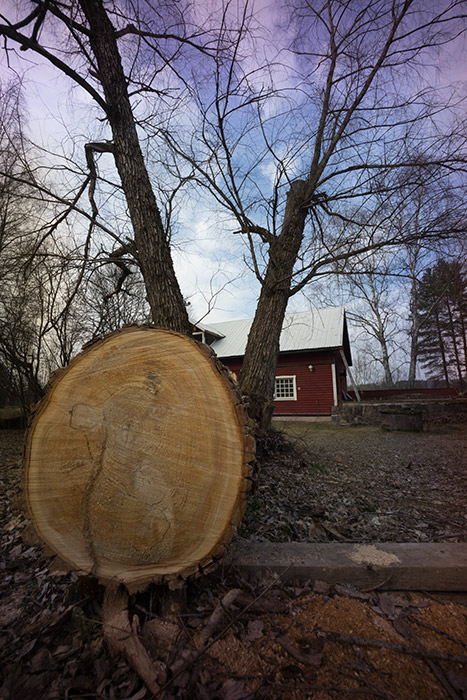
(cropped and resized)
The physics…
As is explained in detail in the article on chromatic aberrations, different wavelengths (colours) of light are liable to behave differently. Generally, those differences are quite minor but in some, extreme circumstances those minor differences may play a large role. This is especially true whenever angles of refraction and angles of incidence are relatively extreme.
Secondly, these kinds of colour casts are a combination of two parts: one is the angle of incidence of light onto the sensor’s/film’s corner areas, and the other is the sensor optics, most importantly its filter stack. Let’s take these in turns:
Shallow angles of incidence
Ever skipped stones on a lake? Then you know that if the stone hits the water in too steep an angle, it will penetrate the surface, and if the angle is shallow enough the stone will skip.
Believe it or not, the same is (almost) true for light hitting an interface (which is a fancy word for a boundary between two different mediums such as air and glass or air and water). But whereas a stone can only either skip or sink, light is different.
The first difference is obviously that in photography, we don’t want photons to skip. We want them to go straight through every lens element. Another difference is in that regular, polychromatic (containing many colours/wavelengths), unpolarised light is a horrendous, chaotic tassel of gazillions of different waveforms/photons wiggling and swinging to and fro (think of it as a gazillion of oscillating stones of slightly various weight and form thrown at once). Whenever those gazillion waveforms/photons hit an interface a share of them will pass through and a share of them will skip. And the steeper the angle of light vs. interface surface (i.e. “angle of incidence”) the more will penetrate and the fewer will skip; the shallower the angle, the more will skip and the fewer will penetrate. Always!
A big part of the improvement in optics we’ve enjoyed during the last ≈75 years has to do with (the initial development and subsequent improvement of) coatings. To coat a lens is to give it a chemical treatment designed with the single purpose of – in all situations – making it easier for light to pass through the interface, thereby making fewer photons skip.
But different kinds of lenses lead to different angles of incidence. Think of it like this: Every lens has what is called an exit pupil. The exit pupil is not only one of those fancy imaginary measurements lens designers come up with to simplify horrendously complicates calculations – you can easily see a lens’ exit pupil. Just take off the lens’ front and rear caps, close down the lens to its smallest aperture, and look through it from behind, preferably against some light. The small bright aperture you see is the exit pupil. All light that passes through the lens to subsequently hit the camera’s film or sensor comes through that pupil (No. I’m not implying that the aperture mechanism equals the exit pupil, but the point/depth at which your eye sees that aperture is, in fact, at the point of the exit pupil). The distance between that exit pupil and the sensor/film plane (and the film/sensor size) defines how shallow the angle of incidence at the film plane is (see illustration below).
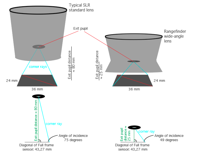
While you might not be able to be certain how deep inside your lens that exit pupil is (given how the air-glass interfaces play tricks with our perception of depth), you can try looking it at different angles, and – by and large – you will quickly be able to notice that wide-angle lenses generally have exit pupils that seem to be farther back (closer to the sensor/film), leading to shallower angles of incidence.
As long as we’re dealing with SLR lenses, this never poses a problem. Given that the exit pupil cannot be farther back than the outer surface of the rearmost lens element, and as the necessities posed by the SLR’s moving mirror1 means that those rearmost lenses are at least 35 mm (often longer) away from the film/sensor plane, this also means that the light rays hitting even the extreme corners of films/sensors always come at relatively steep angles.
But when you’re adapting rangefinder lenses, that not only have a short flange focal distance, but also often protrude out of the mount (into the camera), it may result in exit pupils only ≈20 millimetres from the sensor/film plane and – as an unavoidable result – very shallow angles of incidence.
But – you might rightly ask – these lenses used to work perfectly well with film cameras. What has changed?
The answer is largely based on how sensors work.
Sensor optics and the filter stack
Digital sensors are not film. Most importantly, while film was a thin film (yes, pun intended) coated with photo-reactive particles, exposed to light directly, the photo-reactive pixels (called ‘photosites’) that make up digital imaging sensors are covered by various layers of optics. These optics are collectively referred to as the sensor’s filter stack (also sometimes shortened as sensor stack), and depending on the sensor in question, the optical functions embedded into that filter stack (and its thickness) vary somewhat.
Each photosite must (at a minimum) be covered with a layer to let through only one colour of light (red for red photosites etc.) and a microlens that helps gather light into the sensor well. Thereafter, most sensors employ a layer (or two) to eliminate non-visible light spectra (IR and UV). Most sensors moreover employ an anti-aliasing filter to combat moire, and – finally – a layer of glass simply for protecting the whole shebang. On the whole (based on cameras ‘out there’), the thickness of a sensor’s filter stack may vary from slightly under a millimetre to over four millimetres.
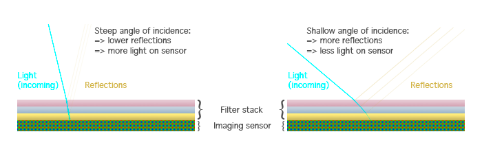
The main issue is based on that the filter stack can (coarse simplification) be conceptualised as a bunch of layers on top of the actual sensor, and while the optical quality of those layers is tremendous, it nevertheless is a bunch of interfaces, that – as you can probably guess – are liable to partially reflect light (and not let everything through) and stray different wavelengths of light differently. If you’re up to some geekery, you can read Roger Ciala’s in-depth analyses here (mind you, these articles don’t even go into extreme rangefinder wide-angles). If this is not the time to harness your inner geek, hopefully the following illustration (a rough approximation) will help.
Note, please: I am obviously simplifying the issue here a bit, because I have not addressed how (combined with shallow incidence angles) some filter stacks seem to be prone to be selective regarding the wavelengths (colours) of light they let through all the way. Because what we do know from optics is that while the wavelength does affect how the ‘photons’ are bent, it does not affect which ‘photons’ skip at an air-glass interface. To be honest, I too am not entirely sure what happens here, but my guess is that – due to the minor differences in how different wavelengths are bent (and keeping in mind that a filter stack is made up of several layers of optics with different optical properties) some wavelengths are more liable than others to get caught up in a phenomenon commonly referred to as total internal reflection.
Examples
I don’t have a bunch of mirrorless cameras lying about (cameras tend to lose value quicker than optics, so I don’t buy cameras for the fun of it). But I do have two cameras known to carry very different sensor filter stacks: a Sony a7R (mk I) and a Sony a7R (mk II). Note that all the following examples are taken with the following settings: Tripod, 2 s delay timer, ISO 100, WB Sunny.
The first pictures I’ll show you are about filter stack -induced vignetting (although vignetting is the topic of another article, these cases are filter stack-related and thus worth mentioning here). Vignetting is commonly an issue when shooting at wider apertures, and can (with most lenses) be effectively addressed simply by stopping down. So when you use your lens wide open, and get a picture like the one upper left below, you naturally assume that you’ll remove that vignetting by stopping down. You’d be surprised, because the level of vignetting stays virtually the same all the way from f/2.8 to f/22.

Granted, the Jupiter 12 is a somewhat special lens. The Jupiter 12 is another Soviet copy of a Zeiss design. Originally designed by Zeiss as the Biogon 35 f/2.8 for Contax rangefinders, the Jupiter 12 was not only available for Kiev rangefinders (the Soviet clone of the prewar Contax rangefinder), but a version in LTM mount was also made for use with the Soviet thread-mount Leica copies (FED and Zorki). The lens is special in that its rear element (alike many rangefinder wide-angles) protrudes far into the camera, resulting in very little clearance between the lens and the film plane and therefore very shallow angles of incidence. This shallow angle is the reason for the massive vignetting visible above (as oblique light rays are less able to penetrate the filter stack).
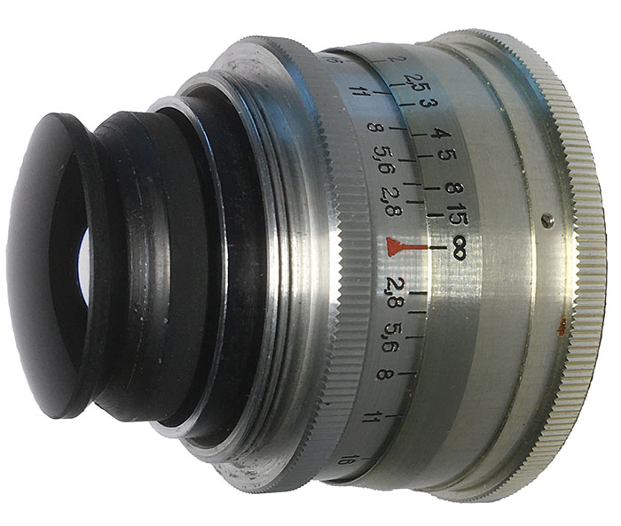
But that vignetting is so massive, that it actually manages to hide another (and less easily addressed) problem – a colour cast. Once you remove that vignetting in post, a reddish/violet colour cast becomes obvious. The reason for this cast is that the sensor filter stack disproportionately precludes some wavelengths from reaching the photosites.
The example given by the Jupiter 12 is not even especially severe, but I wanted to clarify that the issues is limited to a single lens. Next, let’s see how bad colour casts can be!


I need hardly tell you that this is bad. Actually, if you compare these images with the ones at the top of the article, these look almost mild, the reason for which is that (in the blue sky) there are fewer reds to accentuate. Colour casts are more than a nuisance, especially because there are (currently) no approaches to automating their removal. In essence, unless we’re talking about a money shot, manual editing of the colour cast is prohibitively time-consuming (and if I were you, I would not aim for money shots with this rig). Basically, the only simple way to address the colour cast is by cropping (cropping to APS-C size is quite sufficient, but then you’re using a 15 mm lens to produce a 22,5 mm field-of-view).
In contrast, another camera might be a way more effective way to address the issue. The following sextet of pictures shows the result from the Sony a7R’s next generation sibling, the Sony a7R2:

Not only does the a7R2’s sensor stack produce a discernibly milder level of vignetting (milder, but there is sensor-induced vignetting as there is very little difference between the uncorrected vignetting between f/5.6 and f/22 images), it also does not produce any discernible colour cast.
Addressing a colour cast
As noted above, manually addressing a colour cast in an image is not an easy task. It necessitates skilful and patient manual editing in post-production. The best way is therefore to avoid – when possible – a combination of lens and sensor known to produce colour casts.
Therefore, if you have (or plan on getting) wide-angle rangefinder lenses (or invasive SLR fisheyes), you should try to research which sensors are known to produce colour casts. If no trustworthy information is yet available (as often is the case with very new cameras), I heartily recommend going to a shop (with a known-issues-lens) and asking to try out a body before plonking your credit card on the counter.
Finally, and partially as an aside, colour casts typically go hand in hand with another filter stack related issue mentioned in passing above: The same optical characteristics that produce filter stack-induced vignetting and colour casts are also known to produce what is often referred to as corner smearing – a pervasive, directional (away from image centre) blurryness. Moreover, corner smearing often remains even after colour casts are addressed. The following images illustrate the severity of the issue (the crops are from close to an extreme corner). (Both crops desaturated and illumination evened out to heighten comparability).


Right: Nikkor Ai 35/1.4 @ f/5.6 on Sony ⍺7R2
Addressing such shallow incident angle & sensor filter stack -induced corner smearing is by no means easy, but can sometimes be done. One approach is to have your camera’s sensor filter stack modified (expensive, cumbersome, and may lead to issues when using native lenses), while another is achieved through the use of specialised filters mounted in front of the lens. You can read more about these here or go straight to the horse’s mouth.
Footnotes
1 That SLR lenses cannot protrude into the mirror box is a rule that has some exceptions, such as invasive fisheyes)